Biến đổi kỹ thuật hệ thống thủy lực của máy ép thủy lực bốn cột Y32-200T

Four column hydraulic press machine,Y32-200T four-column hydraulic press machine can be used in the processing of metal parts such as punching, deep drawing and flanging. In the actual use process, we found that its scope of application is limited, and it is impossible to perform deep drawing and blanking and multi-directional die forging thermoforming. In order to make full use of the original equipment, it was decided to transform it as a whole and expand its application range on the basis of replacing as few parts as possible. This transformation is mainly based on the Y32-200T four-column hydraulic press machine to add a blank holder and lateral forming device to adapt to multi-directional die forging. The contents of the hydraulic system transformation are as follows: determine the technical parameters of blank holder and lateral forming; The size calculation of the hydraulic cylinder of the side device and the lateral forming hydraulic cylinder, the schematic design of the hydraulic system.
1. Determination of technical parameters
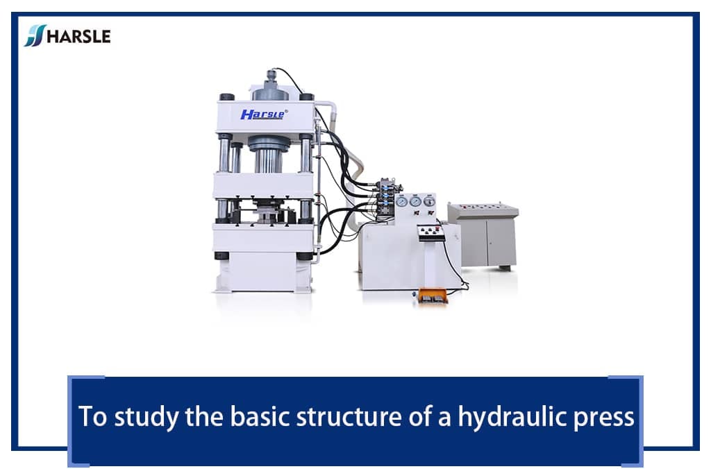
Four column hydraulic press machine,The structure of Y32-200T four-column hydraulic press machine is shown in Figure 1. Its main technical parameters: nominal force 2000kN; ejection force 240kN; slider stroke 800mm; ejection stroke 200mm; table effective area (1000×900) mm; slider empty stroke speed 90mm/s; slider working stroke speed 7~14mm / s; the return speed of the slider is 60mm/s; the maximum distance between the slider and the table is 1000mm, and the working fluid pressure is 25MPa.

Hình 1 —— Sơ đồ máy ép thủy lực rèn khuôn đa hướng
Theo yêu cầu chuyển đổi, hai thiết bị thủy lực giữ trống được thêm vào nền tảng ban đầu. Thiết bị giữ trống được lắp đặt dưới dầm phía trên. Các thông số kỹ thuật chính như sau: lực giữ trống 500kN; khoảng trống làm việc tối đa 200mm; giá đỡ trống làm việc Tốc độ hành trình 7 ~ 14mm / s; tốc độ trở lại thanh trượt 40mm / s; khoảng cách tối đa giữa giá đỡ trống và bàn là 850mm.
Four column hydraulic press machine,Taking into consideration the effective area of the original hydraulic press machine working table and the forming force range of the multi-directional die forging for testing, the technical parameters of the one-sided side forming device are as follows: nominal force 1000kN; slider working stroke 300mm; slider working stroke speed 7~14mm/s; the center height of the lateral forming cylinder is 550mm.
2. Structural design of blank holder hydraulic cylinder and lateral forming hydraulic cylinder
(1) Overview of hydraulic cylinder structure design
The hydraulic cylinder structure design includes the type, size, and support method of the hydraulic cylinder. This is because the hydraulic cylinder is the actuator of the hydraulic press machine, the output power bears the load, and it is also a component that is easy to fail in the hydraulic press machine. Choosing the proper cylinder structure, specifications and support methods of the hydraulic cylinder can not only ensure the accurate action of the hydraulic cylinder, but also extend the service life of the hydraulic cylinder. When designing the hydraulic cylinder structure, the choice of its structural form generally depends on the support mode of the hydraulic cylinder on the hydraulic press machine, and the specifications and models of the hydraulic cylinder are calculated and determined according to the total working pressure of the hydraulic press machine.
(2) Structure design of blank holder
Due to the limitation of the main structure of the Y32-200T hydraulic press machine, the blank holder hydraulic cylinder cannot be fixedly installed on the upper beam, so we choose to install a 150mm thick steel plate on the movable beam, and process through holes on the steel plate. Together, the cylindrical surface of the outer wall of the hydraulic cylinder is installed in cooperation with the through hole in the steel plate. Because it is a small hydraulic press machine, the piston cylinder is used as the blank holder.
1) Calculation of the inner diameter of the blank holder. As known from formula ①, the inner diameter of the hydraulic cylinder is determined by the nominal pressure of the blank holder and the hydraulic fluid pressure of the hydraulic system. The nominal pressure F is 500kN, the hydraulic pressure P = 20MPa, and the calculated D1 is 180mm.
D1 = √4F / πP ①
2) Calculation of the piston diameter of the blank holder. The relationship between the piston diameter of the blank holder and its inner diameter is shown in formula ②, where the quasi is related to the working pressure P. When the working pressure P is greater than or equal to 20 MPa, the quasi = 2.3, so the piston diameter d = 0.75D1, d is rounded to 135mm.
d = D√Φ-1 / φ ②
3) Calculation of the outer diameter of the blank holder. It is known that the inner diameter of the hydraulic cylinder D1 = 55mm. Because the hydraulic cylinder material uses the 35th cylinder, the allowable stress of the material is σ = 200MPa, and the outer diameter of the hydraulic cylinder calculated by formula ③ is 210mm.
D2 = D1√σ / σ-√3P ③
4) Check the return force of the blank holder. The hydraulic cylinder needs to overcome its own gravity, friction and other factors when returning. The general return force is 10% to 20% of the nominal pressure. The return force of the blank holder calculated by formula ④ is 247kN, which meets the design requirements.
F1 = π (D1²-d²) P / 4 ④
(5) Determination of other dimensions of blank holder. Wall thickness: δ = (D2-D1) / 2 = 15mm, cylinder bottom thickness: t1 = (1.5~2) δ, take t1 = 30mm, flange thickness: t2 = (1.5~2) δ, take t2 = 30mm .
(3) Structural design of the lateral forming cylinder
The lateral forming cylinder adopts the symmetrical setting of the piston cylinder and adopts the tie rod to support the connection, the cylinder body is fixed on the lateral support base, and the lateral support base is connected with the hydraulic press machine base. The nominal pressure of the lateral forming cylinder is 1000kN, and the hydraulic pressure is 25MPa. The relevant technical parameters of the lateral forming cylinder can be obtained from the above hydraulic cylinder parameter calculation formula. The technical parameters of the blank holder hydraulic cylinder and the lateral forming cylinder are shown in Table 1.
Table 1——Technical parameters of blank holder and side forming cylinder

3. Hydraulic system design
Thiết kế của hệ thống thủy lực bao gồm hai phần, một là thiết kế hệ thống thủy lực theo phương thẳng đứng bao gồm xi lanh giữ trống và xi lanh chính và xi lanh đẩy, hai là thiết kế hệ thống thủy lực của xi lanh thủy lực tạo hình bên.
(1) Hydraulic circuit design of double-acting hydraulic press machine
Due to consideration of retaining the hydraulic system of the original Y32-200T hydraulic press machine, two hydraulic circuits of blank holder cylinders are added to the original system to form the hydraulic circuit of the double-acting hydraulic press machine.
The working process of the hydraulic press machine in the vertical direction is as follows: The empty stroke of the master cylinder is quickly downward. When the blank holder slides close to the blank, the master cylinder descends slowly. The blank holder provides variable blank holder force and the blank is completed. After that, the system releases the pressure and the main cylinder drives the movable beam back, which rises to a certain distance after the blank holder returns, and then ejects the cylinder to eject the product, completing a working cycle.

1.4.7. Filter 2. Motor 3. Cooler 5. Variable piston pump 6.8.21. Check valve
9.22. Overflow valve 10.11.12.13.15.18.19. Directional valve 14.16.23.24. Filling valve 17. Hydraulic control check valve 20. Balance valve
Figure 2——Vertical hydraulic circuit of hydraulic press machine
Qua hình 2 có thể thấy hệ thống thủy lực sử dụng hệ thống điều khiển tỷ lệ điện thủy lực và điều khiển lập trình PLC. Theo tín hiệu dịch chuyển do hệ thống thiết lập, nó sẽ phát ra các lệnh tương ứng để điều khiển các hành động tuần tự của từng cơ cấu chấp hành theo phương thẳng đứng. Bơm thủy lực là loại bơm pít tông biến thiên đơn, nó cũng đáp ứng các điều kiện làm việc của xi lanh phóng nhanh áp suất thấp và tốc độ chậm áp suất cao của xi lanh chính và xi lanh giữ trống, giúp tiết kiệm năng lượng hệ thống. Để giảm độ rung và tác động của hệ thống trong quá trình chuyển mạch, một van tràn 22 được bổ sung để chống tràn và giảm áp. Việc đảo chiều và dừng của thiết bị giữ trống được điều khiển bởi hai chức năng trung tâm của van 11 và van 12, đó là van đảo chiều ba vị trí bốn chiều kiểu O. Khi điền.
(2) Design of hydraulic system of lateral forming hydraulic cylinder
The lateral forming device is mainly used for the forming of multi-directional hot die forging. Because in the multi-directional hot die forging process, the temperature of the blank has a great influence on the force during forming and the flow line of the metal product after forming, so when forming the hot die forging product, the lateral hydraulic system is required to be able to Quick work to complete the extrusion of the blank, and must have the function of holding pressure. At the same time, due to the different shapes of the left and right sides of the hot die forging parts, the required force and forming time are also different, so the hydraulic system is required to be able to drive the left and right cylinders independently, and the pressure is opposite, Adjustable speed.
Quá trình làm việc của máy ép thủy lực theo phương ngang như sau: xi lanh thủy lực bên trái và bên phải là bộ phận ép đùn nhanh chóng-giữ áp suất xả áp-các xi lanh thủy lực hai bên được rút lại đồng thời.
Hình 3 là sơ đồ hệ thống thủy lực của thiết bị tạo hình bên. Qua hình vẽ có thể thấy rằng xi lanh thủy lực bên trái và bên phải được dẫn động độc lập bởi các bơm biến thiên của chúng, và tốc độ của chúng có thể được điều chỉnh bởi lưu lượng của bơm biến thiên; Giới hạn áp suất tối đa của hệ thống thủy lực của xi lanh bên trái và bên phải; trong hành trình hồi lưu, để giảm tác động trong quá trình chuyển mạch, van giảm áp 8 và 17 được lắp đặt trên hành trình hồi lưu tương ứng. Các xi lanh bên trái và bên phải có thể hoạt động độc lập và giải phóng áp suất, hoặc chúng có thể được kết nối bằng cách chuyển đổi van hướng 21 và 22 để đạt được sự đồng bộ của công việc và giảm áp suất.

1.11. Filter 4.13. Cooler 2.12. Variable piston pump
3.7.15.18. Check valve 6.8.16.17. Overflow valve 9.10.19.20.21.22. Solenoid directional valve
Hình 3 —— Mạch thủy lực thiết bị bên
Từ thiết kế của hệ thống thủy lực, có thể thấy rằng trong quá trình tạo hình khuôn dập đa hướng của máy ép thủy lực, ba quá trình tạo hình sau đây có thể được lựa chọn theo yêu cầu của quá trình: thứ nhất, hướng thẳng đứng được hình thành, sau đó là hướng ngang, và cuối cùng khuôn được mở lên và xuống, Ejection trái và phải; thứ hai, hướng ngang được hình thành trước, và sau đó hướng thẳng đứng được hình thành, và sau đó khuôn được đẩy ra; thứ ba, hướng ngang và hướng dọc được hình thành cùng nhau, và khuôn được đẩy ra.
4. Summary
(1) According to the main technical parameters of the Y32-200 T hydraulic press machine, the technical parameters of the blank holder and lateral forming device are determined on the basis of maximum use of the original equipment.
(2) On this basis, select the type of the corresponding hydraulic cylinder and calculate its main specifications and model parameters.
(3) According to the requirements of working conditions, the hydraulic system diagram of the vertical molding direction and the hydraulic system diagram of the lateral molding direction are designed, and three process plans for multi-directional die forging are proposed.
Sau khi biến đổi tổng thể của máy ép thủy lực, nó được áp dụng cho khuôn đúc đa hướng thực tế tạo hình nóng cho thanh kết nối, có thể đáp ứng các yêu cầu công nghệ tạo hình sản phẩm và phạm vi ứng dụng của máy ép thủy lực đã được rất nhiều được cải thiện.