Trasformazione tecnica del sistema idraulico della pressa idraulica a quattro colonne Y32-200T

Four column hydraulic press machine,Y32-200T four-column hydraulic press machine can be used in the processing of metal parts such as punching, deep drawing and flanging. In the actual use process, we found that its scope of application is limited, and it is impossible to perform deep drawing and blanking and multi-directional die forging thermoforming. In order to make full use of the original equipment, it was decided to transform it as a whole and expand its application range on the basis of replacing as few parts as possible. This transformation is mainly based on the Y32-200T four-column hydraulic press machine to add a blank holder and lateral forming device to adapt to multi-directional die forging. The contents of the hydraulic system transformation are as follows: determine the technical parameters of blank holder and lateral forming; The size calculation of the hydraulic cylinder of the side device and the lateral forming hydraulic cylinder, the schematic design of the hydraulic system.
1. Determination of technical parameters
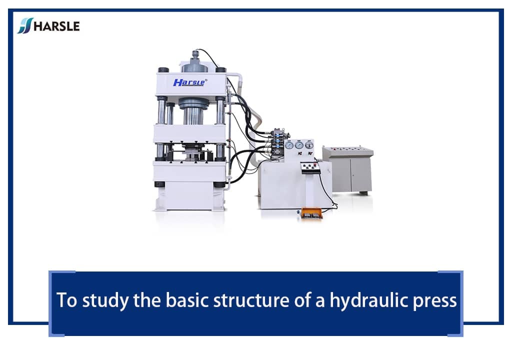
Four column hydraulic press machine,The structure of Y32-200T four-column hydraulic press machine is shown in Figure 1. Its main technical parameters: nominal force 2000kN; ejection force 240kN; slider stroke 800mm; ejection stroke 200mm; table effective area (1000×900) mm; slider empty stroke speed 90mm/s; slider working stroke speed 7~14mm / s; the return speed of the slider is 60mm/s; the maximum distance between the slider and the table is 1000mm, and the working fluid pressure is 25MPa.

Figura 1——Diagramma schematico della pressa idraulica multidirezionale per fucinatura
A seconda delle esigenze di trasformazione, alla fondazione originaria vengono aggiunti due dispositivi idraulici di trattenimento del grezzo. Il dispositivo di trattenimento del grezzo è installato sotto la trave superiore. I principali parametri tecnici sono i seguenti: forza di tenuta del grezzo 500kN; corsa massima di lavoro del premilamiera 200mm; lavoro del premilamiera Velocità della corsa 7~14mm/s; velocità di ritorno del cursore 40mm/s; la distanza massima tra il premilamiera e il tavolo è di 850 mm.
Four column hydraulic press machine,Taking into consideration the effective area of the original hydraulic press machine working table and the forming force range of the multi-directional die forging for testing, the technical parameters of the one-sided side forming device are as follows: nominal force 1000kN; slider working stroke 300mm; slider working stroke speed 7~14mm/s; the center height of the lateral forming cylinder is 550mm.
2. Structural design of blank holder hydraulic cylinder and lateral forming hydraulic cylinder
(1) Overview of hydraulic cylinder structure design
The hydraulic cylinder structure design includes the type, size, and support method of the hydraulic cylinder. This is because the hydraulic cylinder is the actuator of the hydraulic press machine, the output power bears the load, and it is also a component that is easy to fail in the hydraulic press machine. Choosing the proper cylinder structure, specifications and support methods of the hydraulic cylinder can not only ensure the accurate action of the hydraulic cylinder, but also extend the service life of the hydraulic cylinder. When designing the hydraulic cylinder structure, the choice of its structural form generally depends on the support mode of the hydraulic cylinder on the hydraulic press machine, and the specifications and models of the hydraulic cylinder are calculated and determined according to the total working pressure of the hydraulic press machine.
(2) Structure design of blank holder
Due to the limitation of the main structure of the Y32-200T hydraulic press machine, the blank holder hydraulic cylinder cannot be fixedly installed on the upper beam, so we choose to install a 150mm thick steel plate on the movable beam, and process through holes on the steel plate. Together, the cylindrical surface of the outer wall of the hydraulic cylinder is installed in cooperation with the through hole in the steel plate. Because it is a small hydraulic press machine, the piston cylinder is used as the blank holder.
1) Calculation of the inner diameter of the blank holder. As known from formula ①, the inner diameter of the hydraulic cylinder is determined by the nominal pressure of the blank holder and the hydraulic fluid pressure of the hydraulic system. The nominal pressure F is 500kN, the hydraulic pressure P = 20MPa, and the calculated D1 is 180mm.
D1 = √4F / πP ①
2) Calculation of the piston diameter of the blank holder. The relationship between the piston diameter of the blank holder and its inner diameter is shown in formula ②, where the quasi is related to the working pressure P. When the working pressure P is greater than or equal to 20 MPa, the quasi = 2.3, so the piston diameter d = 0.75D1, d is rounded to 135mm.
d = D√Φ-1 / φ ②
3) Calculation of the outer diameter of the blank holder. It is known that the inner diameter of the hydraulic cylinder D1 = 55mm. Because the hydraulic cylinder material uses the 35th cylinder, the allowable stress of the material is σ = 200MPa, and the outer diameter of the hydraulic cylinder calculated by formula ③ is 210mm.
D2 = D1√σ / σ-√3P ③
4) Check the return force of the blank holder. The hydraulic cylinder needs to overcome its own gravity, friction and other factors when returning. The general return force is 10% to 20% of the nominal pressure. The return force of the blank holder calculated by formula ④ is 247kN, which meets the design requirements.
F1 = π (D1²-d²) P / 4 ④
(5) Determination of other dimensions of blank holder. Wall thickness: δ = (D2-D1) / 2 = 15mm, cylinder bottom thickness: t1 = (1.5~2) δ, take t1 = 30mm, flange thickness: t2 = (1.5~2) δ, take t2 = 30mm .
(3) Structural design of the lateral forming cylinder
The lateral forming cylinder adopts the symmetrical setting of the piston cylinder and adopts the tie rod to support the connection, the cylinder body is fixed on the lateral support base, and the lateral support base is connected with the hydraulic press machine base. The nominal pressure of the lateral forming cylinder is 1000kN, and the hydraulic pressure is 25MPa. The relevant technical parameters of the lateral forming cylinder can be obtained from the above hydraulic cylinder parameter calculation formula. The technical parameters of the blank holder hydraulic cylinder and the lateral forming cylinder are shown in Table 1.
Table 1——Technical parameters of blank holder and side forming cylinder

3. Hydraulic system design
Il progetto dell'impianto idraulico comprende due parti, una è la progettazione dell'impianto idraulico nella direzione verticale composta dal cilindro di trattenimento del grezzo e dal cilindro principale e dal cilindro di espulsione, e l'altra è la progettazione dell'impianto idraulico del cilindro idraulico di formatura laterale.
(1) Hydraulic circuit design of double-acting hydraulic press machine
Due to consideration of retaining the hydraulic system of the original Y32-200T hydraulic press machine, two hydraulic circuits of blank holder cylinders are added to the original system to form the hydraulic circuit of the double-acting hydraulic press machine.
The working process of the hydraulic press machine in the vertical direction is as follows: The empty stroke of the master cylinder is quickly downward. When the blank holder slides close to the blank, the master cylinder descends slowly. The blank holder provides variable blank holder force and the blank is completed. After that, the system releases the pressure and the main cylinder drives the movable beam back, which rises to a certain distance after the blank holder returns, and then ejects the cylinder to eject the product, completing a working cycle.

1.4.7. Filter 2. Motor 3. Cooler 5. Variable piston pump 6.8.21. Check valve
9.22. Overflow valve 10.11.12.13.15.18.19. Directional valve 14.16.23.24. Filling valve 17. Hydraulic control check valve 20. Balance valve
Figure 2——Vertical hydraulic circuit of hydraulic press machine
Si può vedere dalla Figura 2 che il sistema idraulico utilizza un sistema di controllo proporzionale elettroidraulico e un controllo di programmazione PLC. In base al segnale di spostamento impostato dal sistema, invia i comandi corrispondenti per controllare le azioni sequenziali di ciascun attuatore in direzione verticale. La pompa idraulica è un'unica pompa a pistoni variabile, che soddisfa anche le condizioni di lavoro del cilindro di espulsione rapida a bassa pressione e la bassa velocità ad alta pressione del cilindro principale e del cilindro premilamiera, risparmiando energia nel sistema. Per ridurre le vibrazioni e l'impatto del sistema durante la commutazione, viene aggiunta una valvola di troppopieno 22 per il troppopieno e lo scarico della pressione. L'inversione e l'arresto del dispositivo di trattenimento del grezzo sono controllati dalle due funzioni centrali della valvola 11 e della valvola 12, che sono valvole di inversione a quattro vie a tre posizioni di tipo O. Durante il riempimento.
(2) Design of hydraulic system of lateral forming hydraulic cylinder
The lateral forming device is mainly used for the forming of multi-directional hot die forging. Because in the multi-directional hot die forging process, the temperature of the blank has a great influence on the force during forming and the flow line of the metal product after forming, so when forming the hot die forging product, the lateral hydraulic system is required to be able to Quick work to complete the extrusion of the blank, and must have the function of holding pressure. At the same time, due to the different shapes of the left and right sides of the hot die forging parts, the required force and forming time are also different, so the hydraulic system is required to be able to drive the left and right cylinders independently, and the pressure is opposite, Adjustable speed.
Il processo di lavoro della pressa idraulica in direzione orizzontale è il seguente: i cilindri idraulici sinistro e destro vengono fatti avanzare rapidamente - i pezzi estrusi - mantengono la pressione - rilasciano la pressione - i cilindri idraulici su entrambi i lati vengono retratti contemporaneamente.
La figura 3 è lo schema dell'impianto idraulico del dispositivo di formatura laterale. Si può vedere dalla figura che i cilindri idraulici sinistro e destro sono azionati indipendentemente dalle loro pompe variabili, e la loro velocità può essere regolata dalla portata della pompa variabile; Limitare la pressione massima dell'impianto idraulico dei cilindri sinistro e destro; durante la corsa di ritorno, per ridurre l'impatto durante la commutazione, sulla corsa di ritorno sono installate valvole di sfiato 8 e 17 rispettivamente. I cilindri sinistro e destro possono lavorare indipendentemente e scaricare la pressione, oppure possono essere collegati commutando le valvole direzionali 21 e 22 per ottenere la sincronizzazione del lavoro e dello scarico della pressione.

1.11. Filter 4.13. Cooler 2.12. Variable piston pump
3.7.15.18. Check valve 6.8.16.17. Overflow valve 9.10.19.20.21.22. Solenoid directional valve
Figura 3——Circuito idraulico del dispositivo laterale
Dalla progettazione del sistema idraulico, si può vedere che nel processo di formatura per pressofusione multidirezionale della pressa idraulica, è possibile selezionare i seguenti tre processi di formatura in base ai requisiti del processo: in primo luogo, viene formata la direzione verticale, quindi la direzione orizzontale e infine lo stampo viene aperto su e giù, espulsione sinistra e destra; in secondo luogo, viene formata prima la direzione orizzontale, quindi viene formata la direzione verticale e quindi lo stampo viene espulso; in terzo luogo, la direzione orizzontale e la direzione verticale vengono formate insieme e lo stampo viene espulso.
4. Summary
(1) According to the main technical parameters of the Y32-200 T hydraulic press machine, the technical parameters of the blank holder and lateral forming device are determined on the basis of maximum use of the original equipment.
(2) On this basis, select the type of the corresponding hydraulic cylinder and calculate its main specifications and model parameters.
(3) According to the requirements of working conditions, the hydraulic system diagram of the vertical molding direction and the hydraulic system diagram of the lateral molding direction are designed, and three process plans for multi-directional die forging are proposed.
Dopo la trasformazione complessiva della pressa idraulica, viene applicata all'effettiva formatura a caldo multidirezionale della biella, che può soddisfare i requisiti tecnologici della formatura del prodotto e la gamma di applicazioni della pressa idraulica è stata notevolmente migliorato.